Electromechanical Design
Project design portfolio for course ME 360
Project design portfolio for course ME 360
The aim of this project was to create a motion system with 2.5 degrees of freedom with a specialized end effector. Our idea was to design an automatic envelope sealer that would dip a brush in water and wet the edge of an envelope. The envelope could then be removed and sealed. Ultimately, this system could be used in a larger-scale operation in conjunction with a number of systems to load and fold the envelopes.
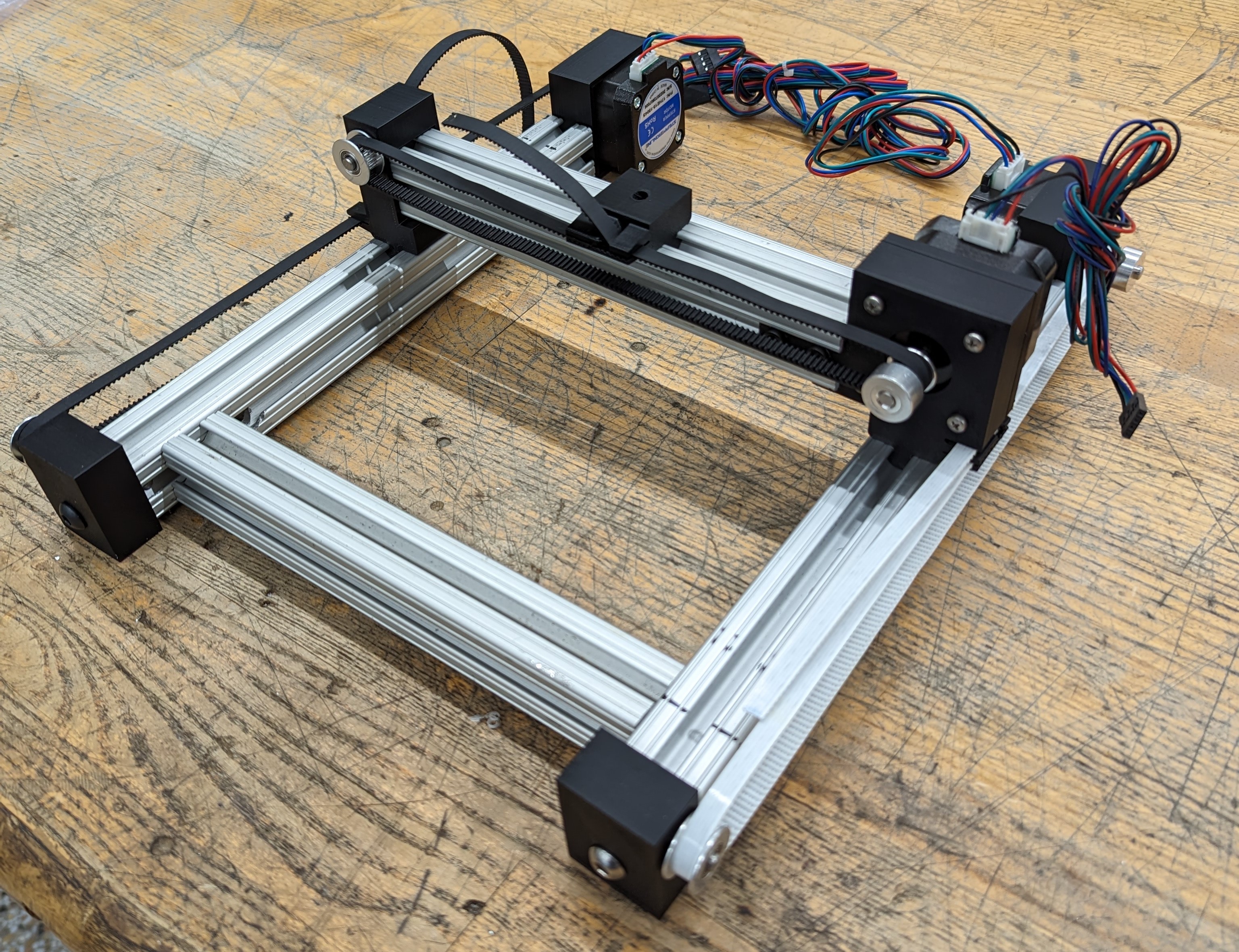
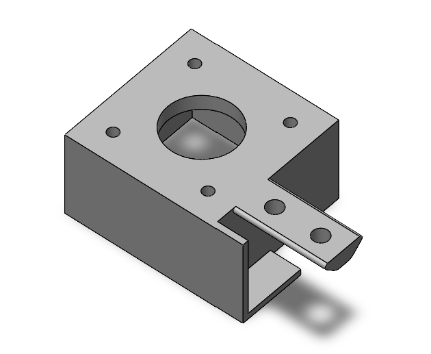
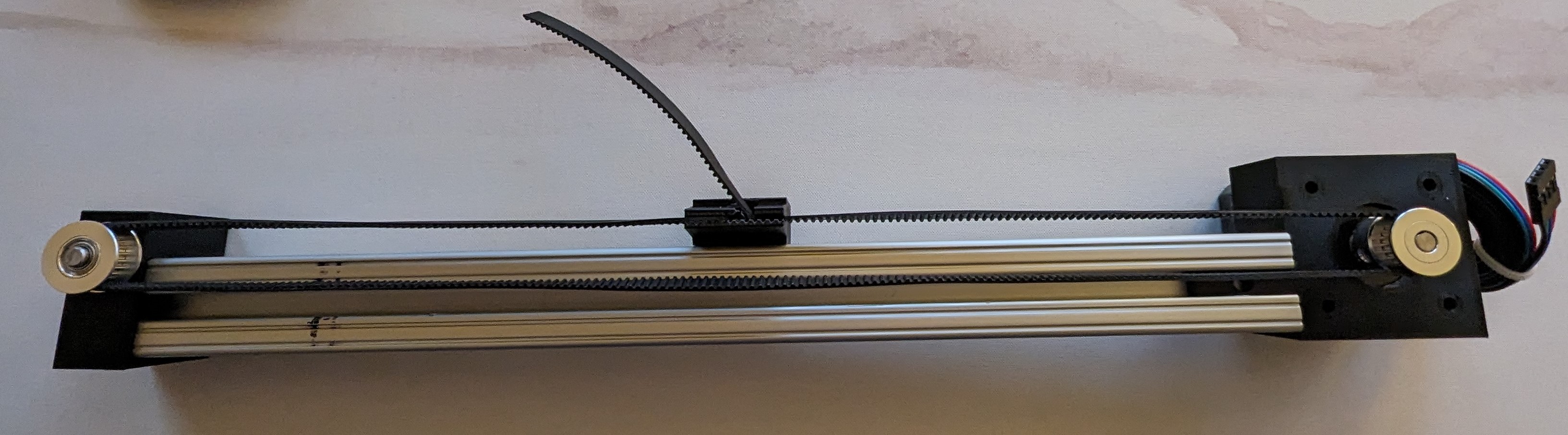
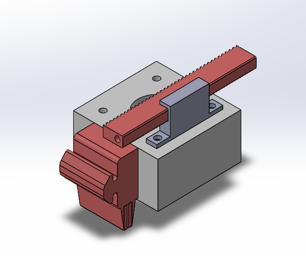
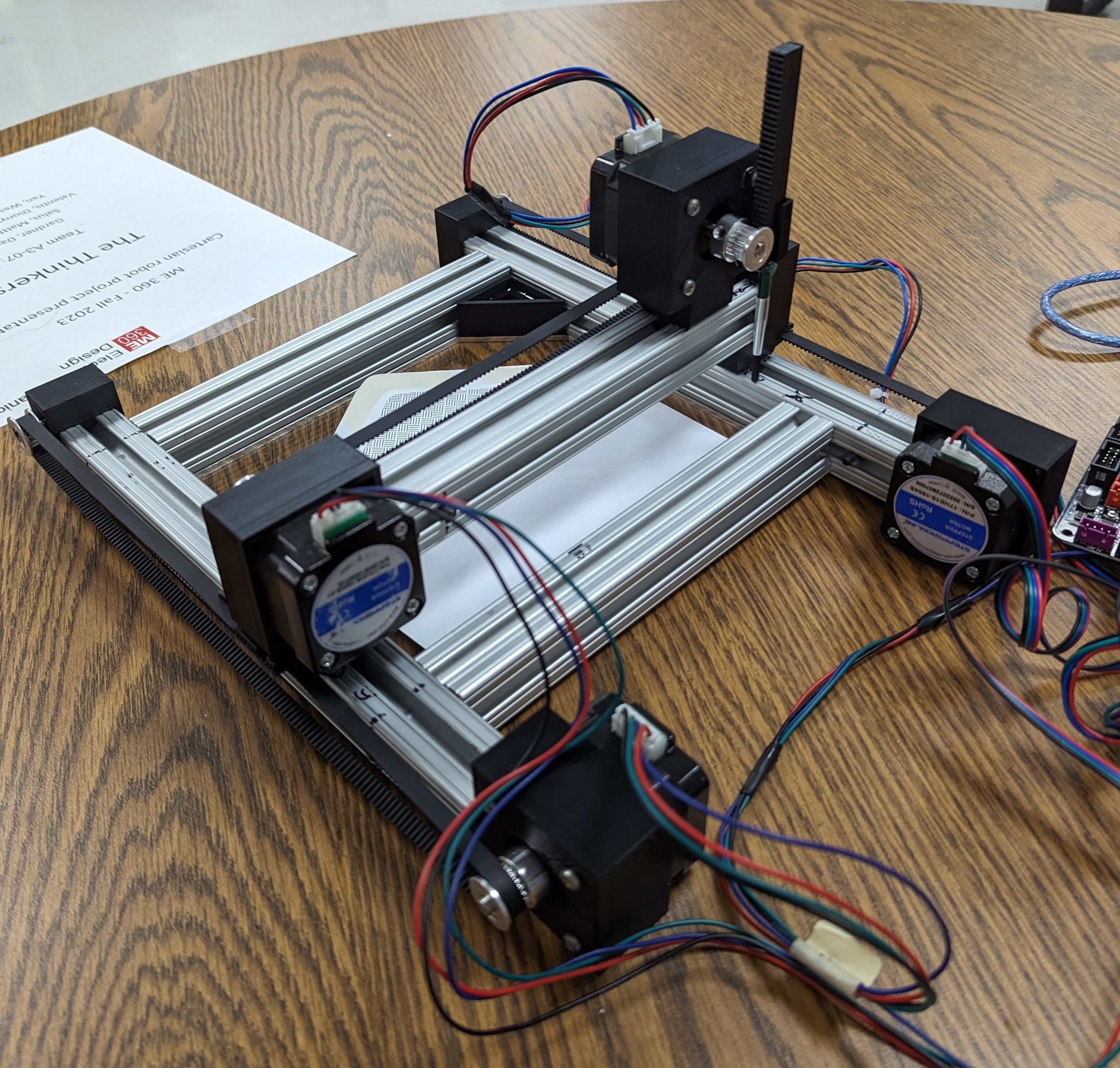
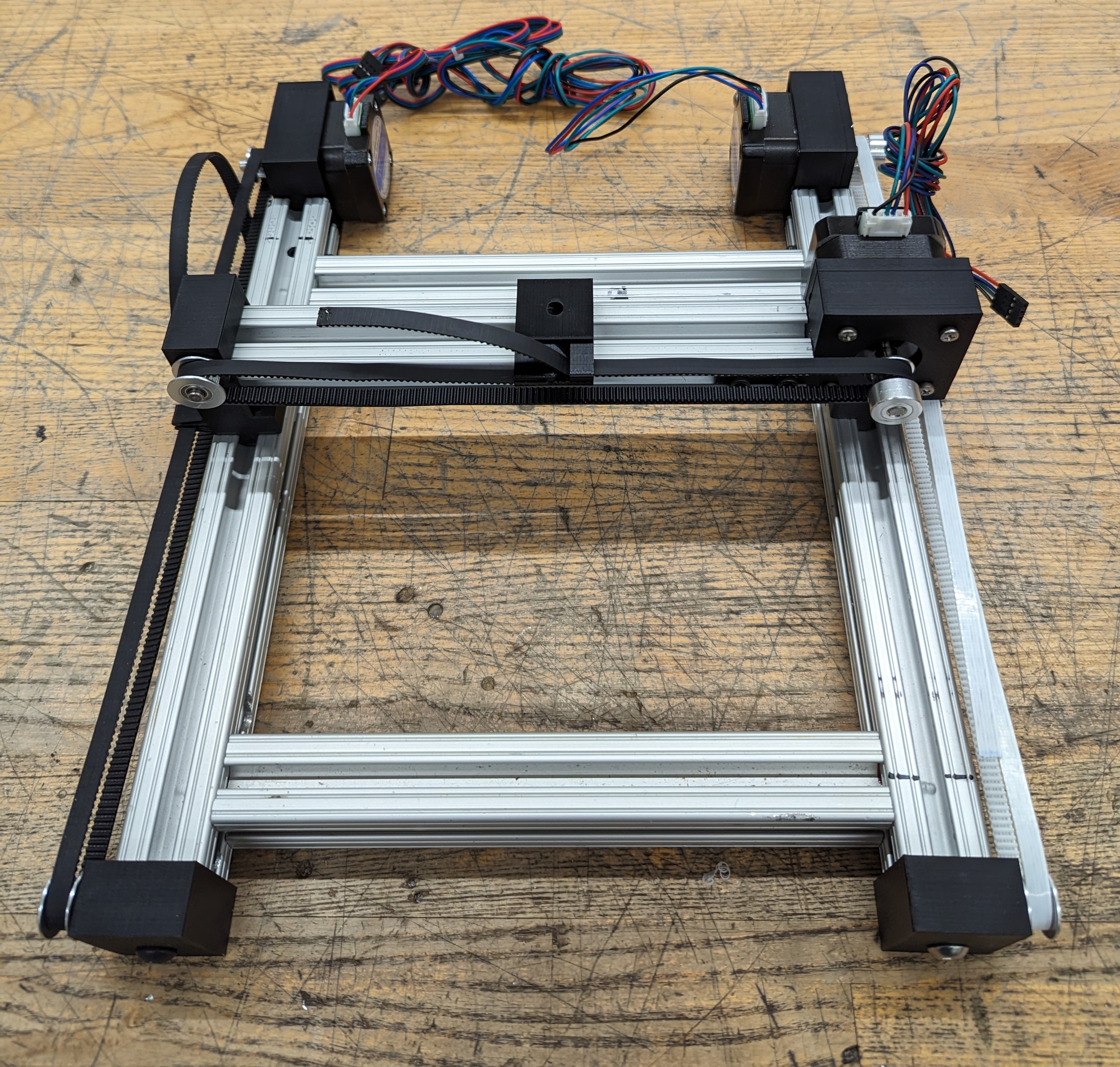
Each state of the motion system consisted of a single stepper motor, bearing, timing belt, and an aluminum extrusion. The motor and bearing were mounted to the extrusion with custom 3D-printed brackets.
The motor mount was fastened to the bar using a t-slot extrusion and a screw. The bearing mount was then screwed directly into the end of the aluminum bar, and the timing belt was connected to a moving piece on the top face of the bar.
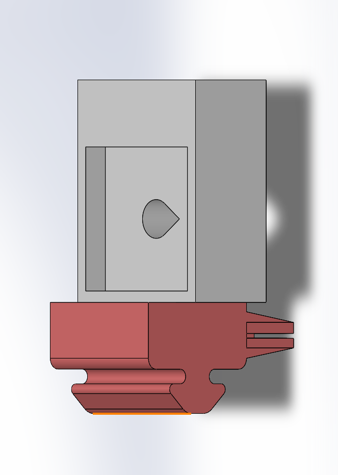
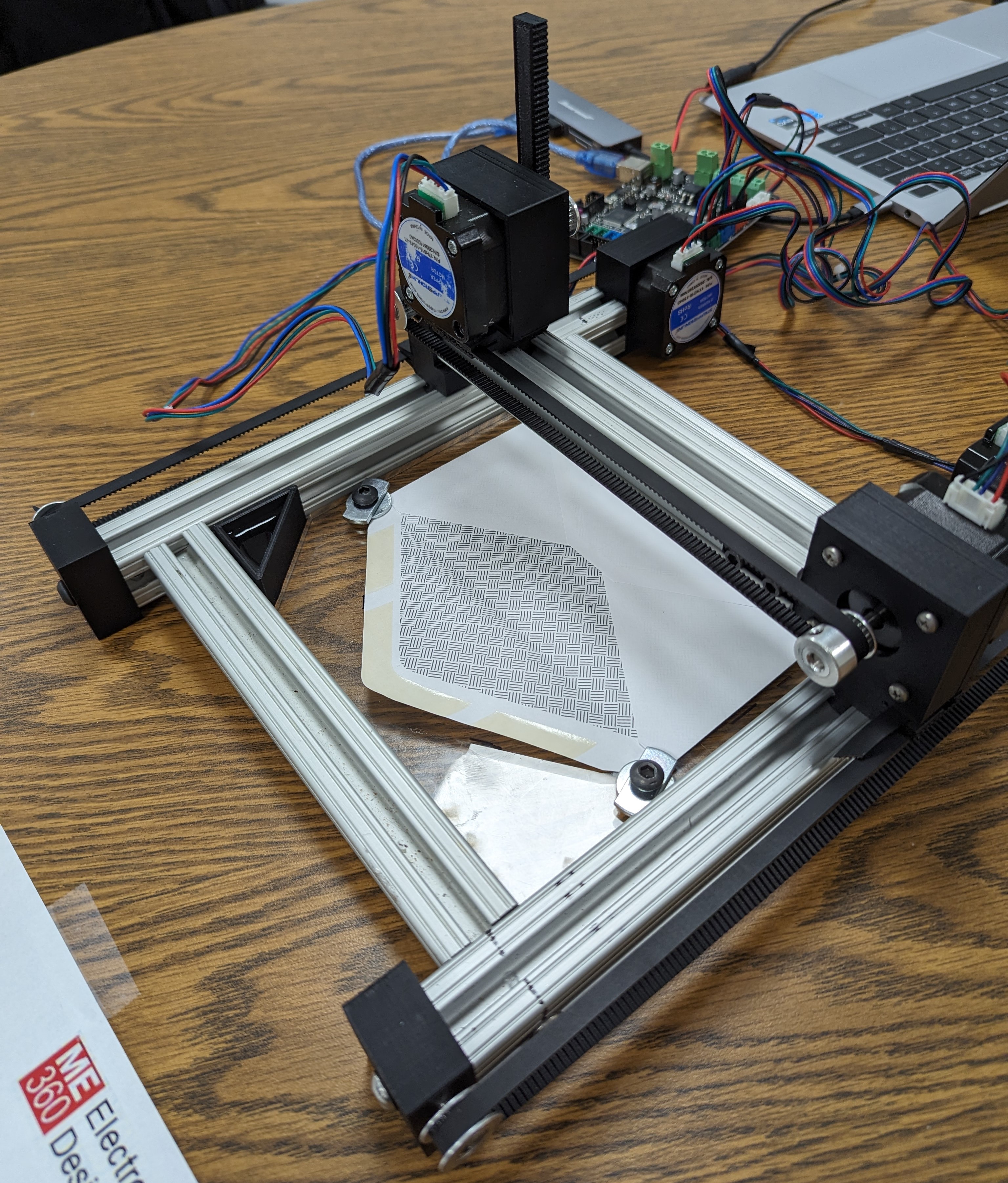
The final assembly of the automatic envelope sealer consisted of three single-stage assemblies and a custom end effector, which utilized a fourth stepper motor.
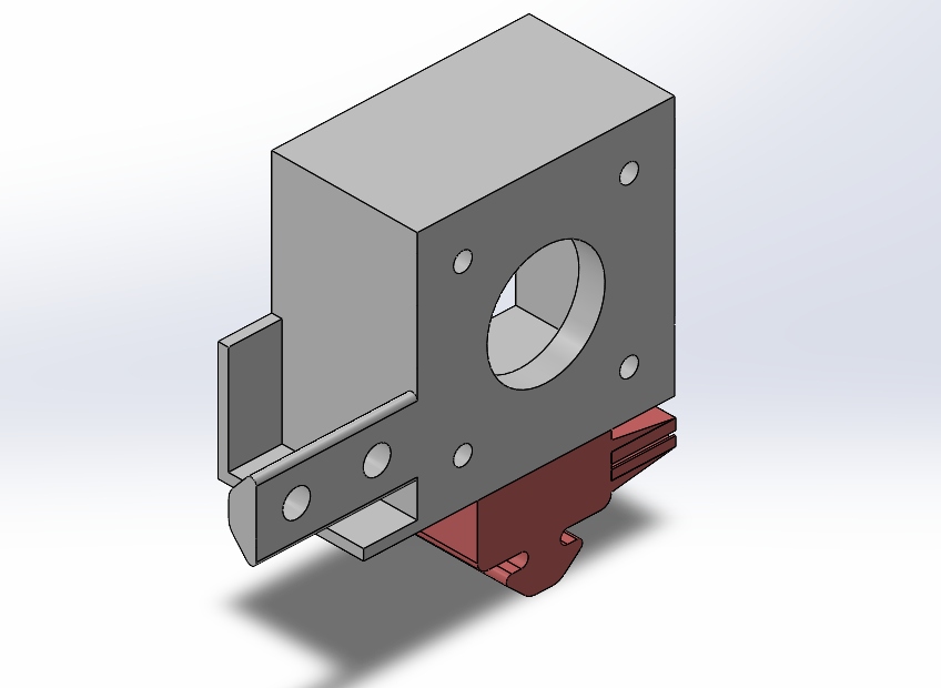
Each of the single-stage assemblies was secured using additional pieces of aluminum extrusion, which formed the workspace of the end effector and the place where the envelope and water dish would be placed. Specialized motor and bearing mounts were created to support the movement of one of the single stages. The end effector assembly was derived from the original motor mount design but modified to support a 3D-printed brush head.
Once we had defined the end effector workspace, an acrylic envelope mount was made to hold the envelope securely. A 3D-printed water cup was then placed in the corner of the workspace in a location that was most accessible to the end effector.
We used a microcontroller with functionality similar to that of an Arduino Mega to control all four motors on the assembly. The motion was defined using a custom G-code and was uploaded directly to the microcontroller. This code could be altered in the future to accommodate any shape of an envelope that fits inside the end effector workspace.
This project required the application of many practical engineering skills in the integration and control of multiple motors into a single 2.5 DOF motion system. The design of the motor mounts, bearing mounts, and end effector reinforced the importance of practical design and adherence to the DFM rules for 3D printing. Fastener choice and integration were also a central focus of the project, as the motion system needed to be functional and robust. Finally, the coordination and control of multiple motors and moving components using a microcontroller and custom G-code is a skill that explores open-loop control. This project summarizes the central principles of the electromechanical design process and emphasizes skills that are essential to every product design exercise.
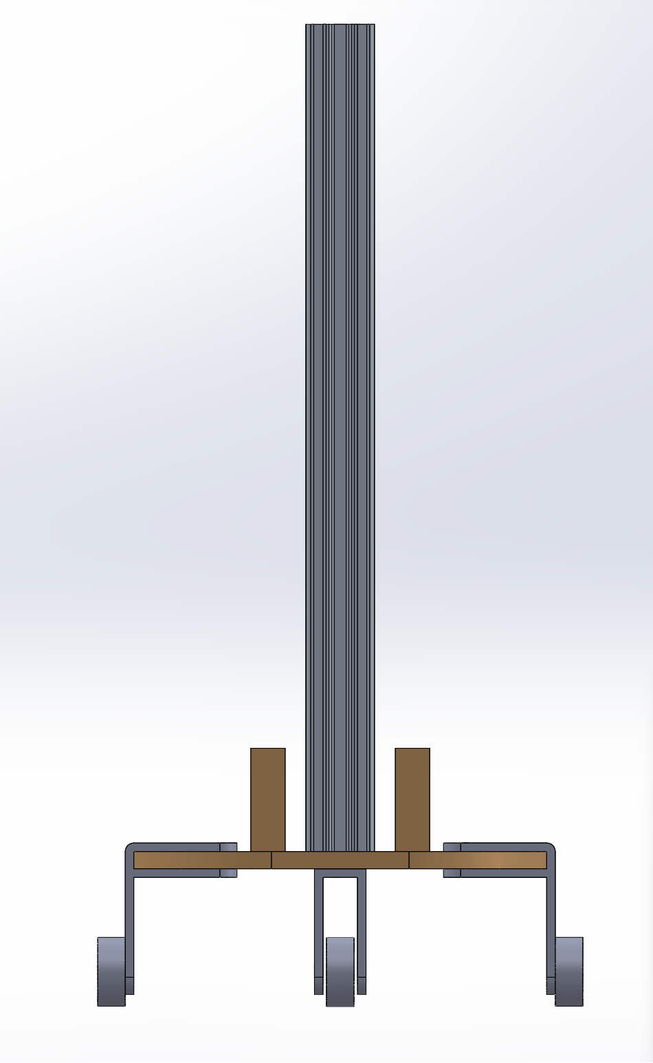
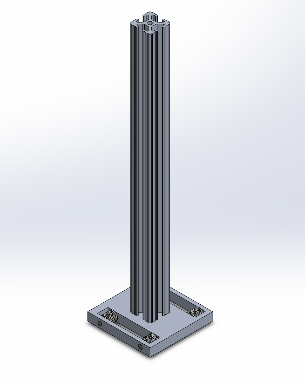
The aim of this project was to move a free-standing 1ft aluminum bar a distance of 10 feet as fast as possible using a simple rotary motor. In order to achieve this goal, multiple cart designs needed to be modeled and tested to determine which would allow the bar to move the required distance in the least amount of time possible. The fastest way to test each of the designs was by using SolidWorks's simulation tools.
The design that I tested was a three-wheeled cart with a flat surface that moved by connecting the front wheel of the cart to the rotary motor. The simulation yielded the fastest time of 10 seconds.
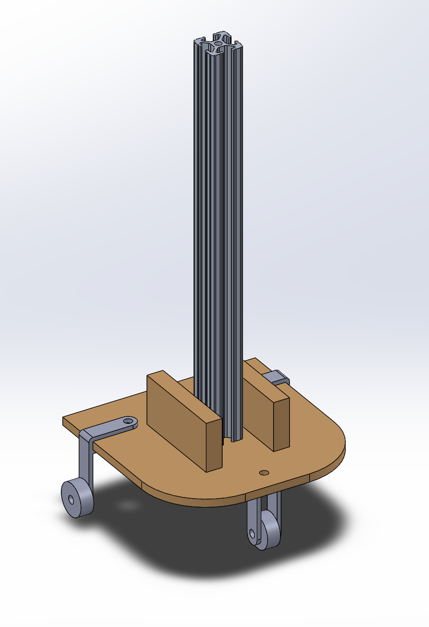
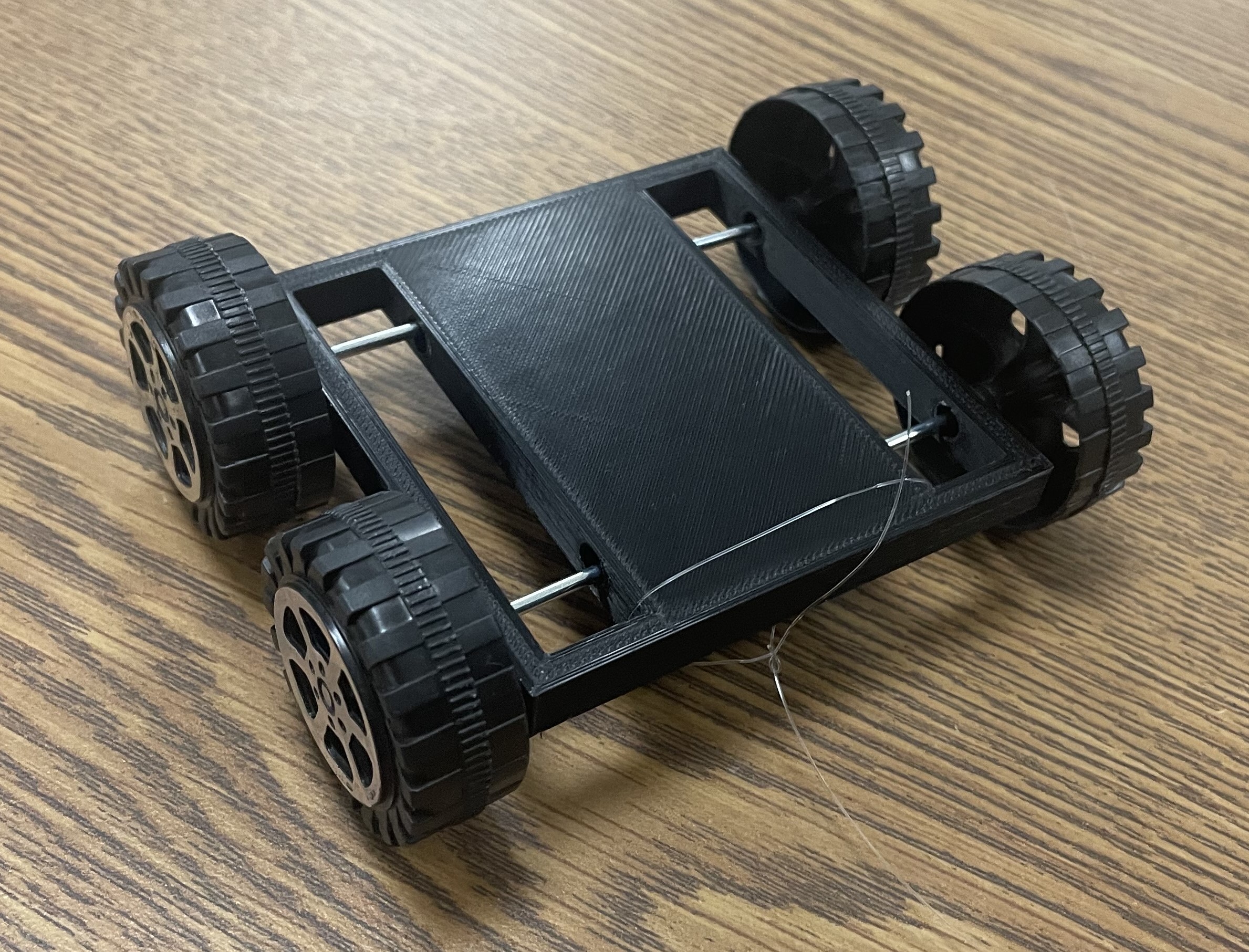
After multiple cart designs had been simulated, our group decided on a design that consisted of two components: the cart and the motor assembly.
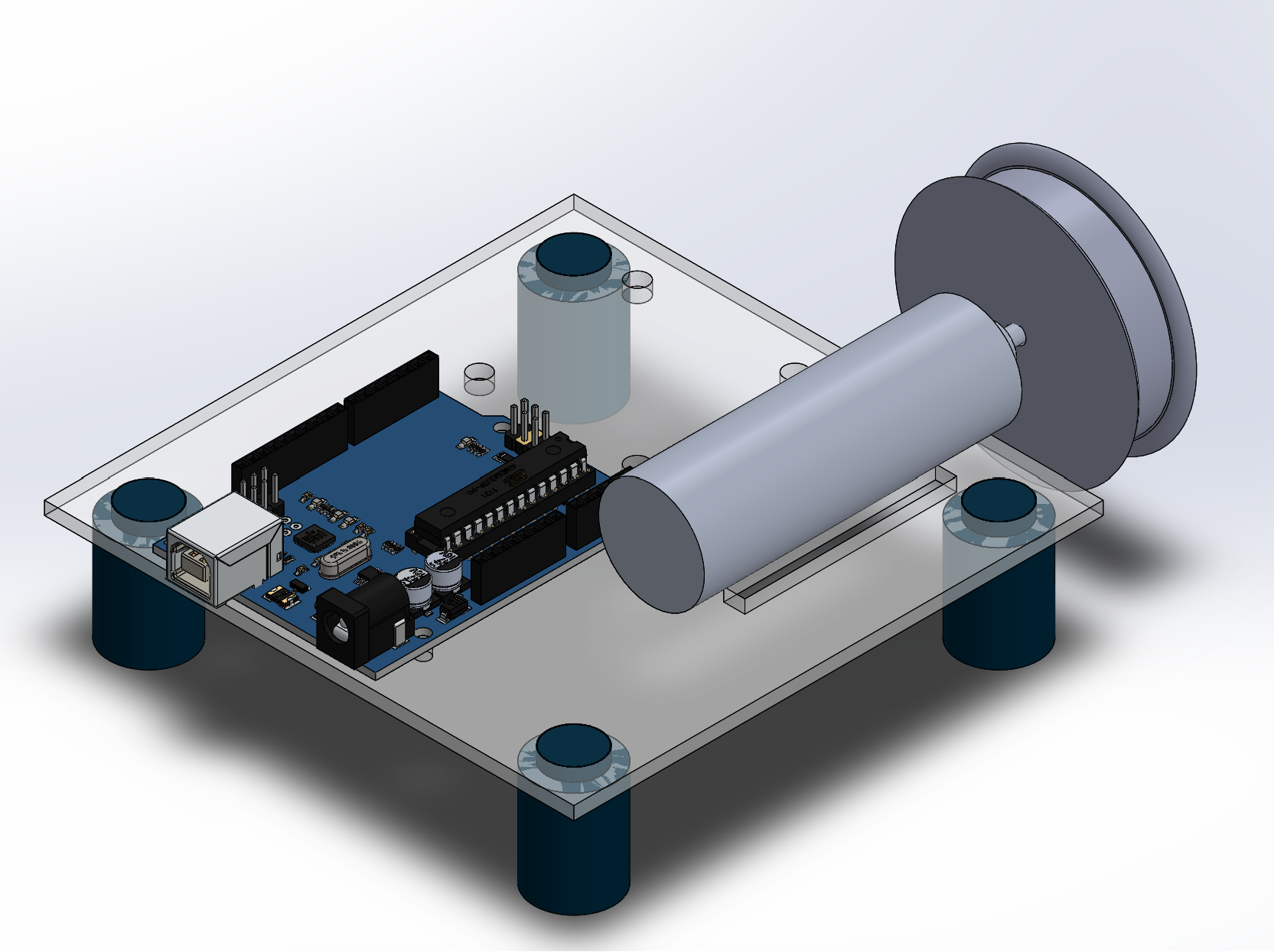
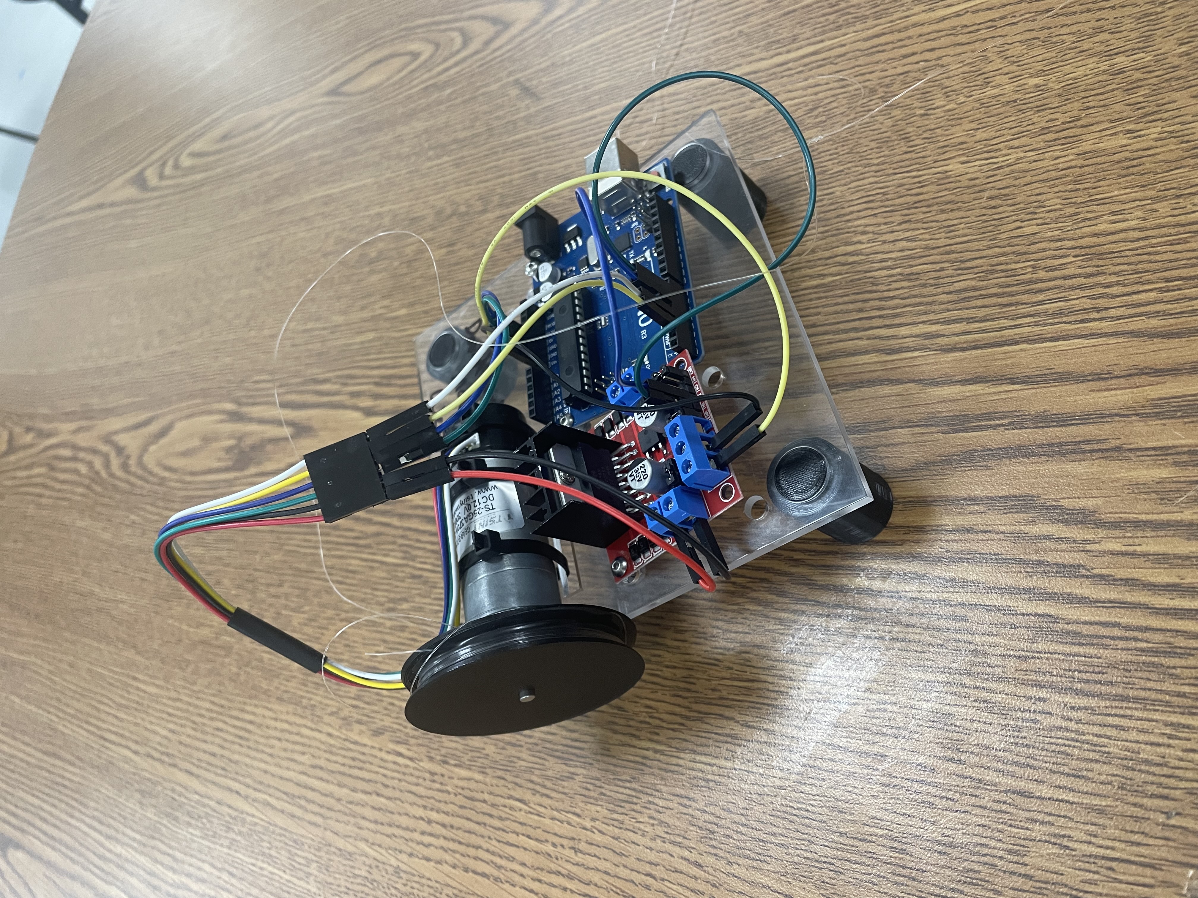
The cart, on top of which rested the aluminum bar, was 3-D printed and connected to the motor assembly using a thin string. The motor assembly was placed at the end of the cart's path and consisted of the motor, the Arduino microcontroller, and a speed controller.
As the motor rotated, the string would wind around the motor and pull the bar and cart to the end of the track. This design was chosen mainly for its simple design, manufacturing process, and assembly. The Arduino was used to control the speed of the motor and accelerate the cart at the fastest rate possible without tipping the bar. The Solidworks simulation also yielded a theoretical completion time of 9 seconds.
After the cart had been assembled, it was tested in a practical environment. While the cart was able to move the bar the required distance in around 10 seconds, there were multiple flaws in the design that became visible in the testing phase of this project.
Although the modular cart design allowed for simple manufacturing and assembly, the design limited the control of the cart. Without having the motor directly drive the motion of the cart, there was no way to slow the cart down actively. This factor decreased the possible speed of the cart as it could not be accelerated for as long as we had control of the cart's deceleration. Additionally, the small size of the cart, while being good for manufacturing times, was not big enough to handle large movements from the bar. This led to less reliability in our trials due to an uneven floor surface, which was not accounted for in the simulations.
This project highlighted many skills that are essential to the design engineering process. Advanced computational tools such as Solidworks simulations were used in the design process to validate ideas and the project's intents. Different closed-loop control strategies were trialed in order to determine how to most quickly and stably control the speed of the cart in order to move the bar the required distance without it falling. Finally, this project focused on the skills required to create a physical prototype from a novel design in order to test the validity of the design, assess how well the simulations compared to the practical tests, and analyze the results in order to identify changes that need to be made in order to improve the overall design for the next iteration.
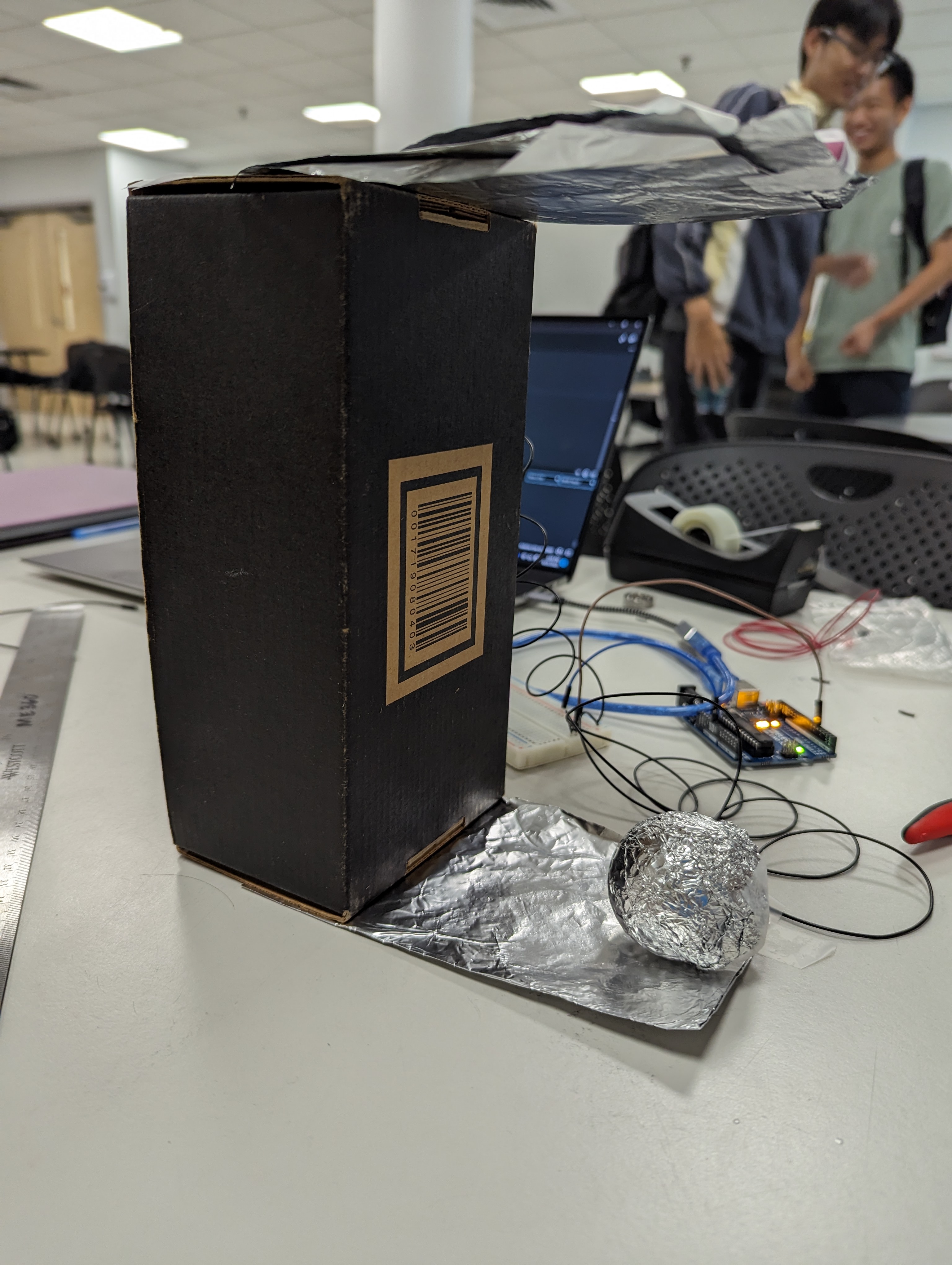
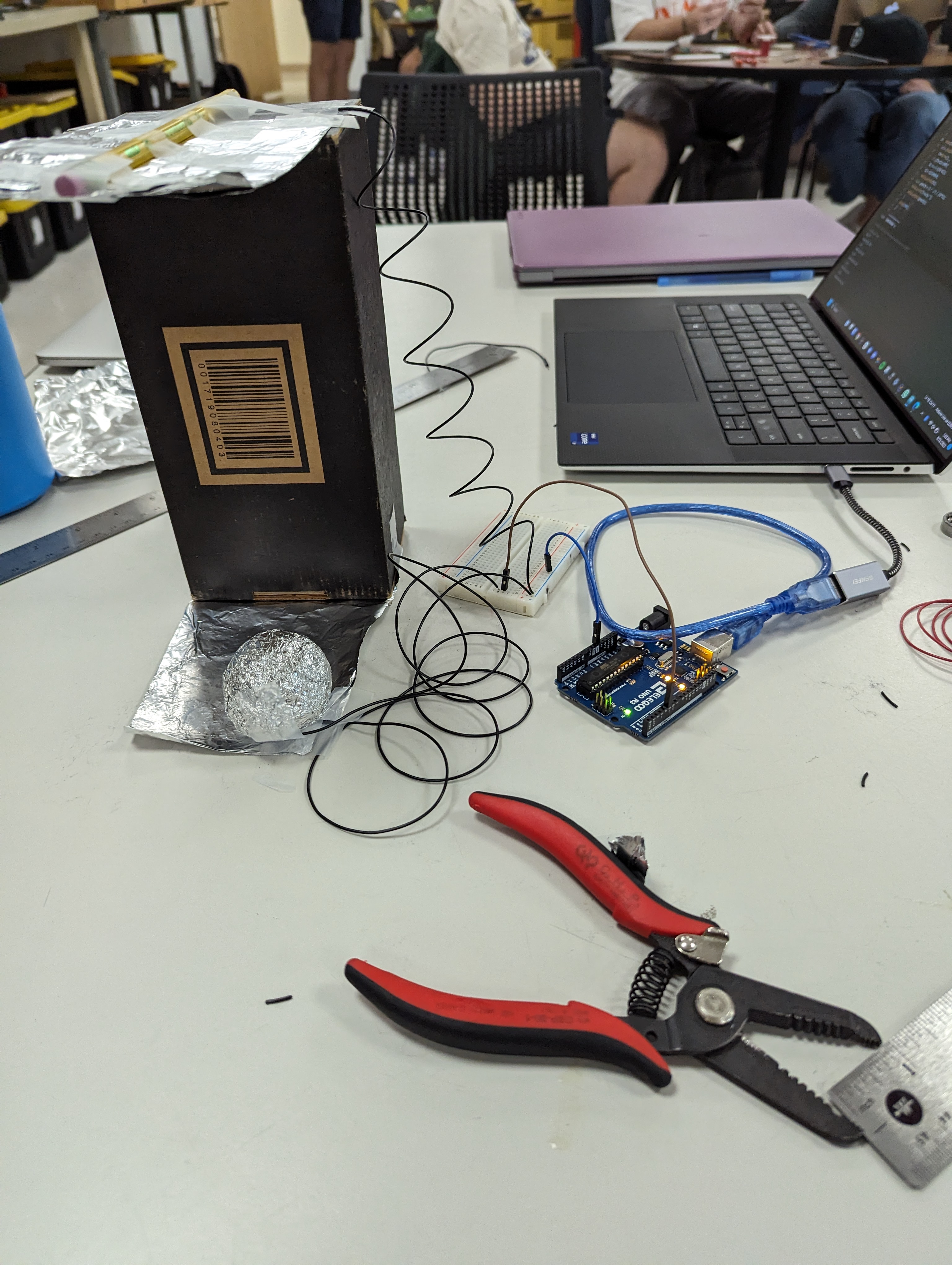
This project aimed to produce a circuit that could accurately measure the acceleration due to gravity using a golf ball and an Arduino microcontroller. The golf ball was first covered in aluminum foil and connected by a wire to the microcontroller. Next, the top and bottom plates, also constructed of aluminum foil, were also connected to the same pin on the microcontroller. Treating the circuit as a simple switch allowed for the circuit to be completed when the golf ball was touching either plate. Finally, the golf ball was dropped from the top plate onto the bottom plate. The microcontroller recorded the time that the circuit was not completed and performed a simple calculation using the distance the ball traveled and the time it took to calculate the acceleration due to gravity. The results of our circuit produced a value of 10m/s^2 as the acceleration due to gravity, which is extremely close to the actual value. This project focused on harnessing fast mechanical-electrical interfacing. This principle can be found in many applications, such as robotics, automotive systems, and wearable electronic devices.
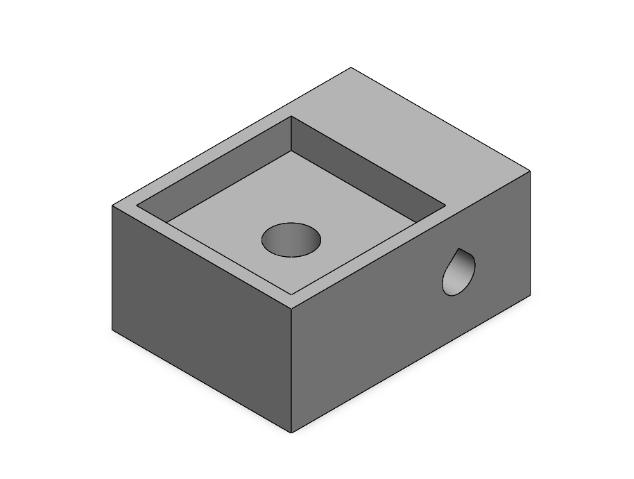
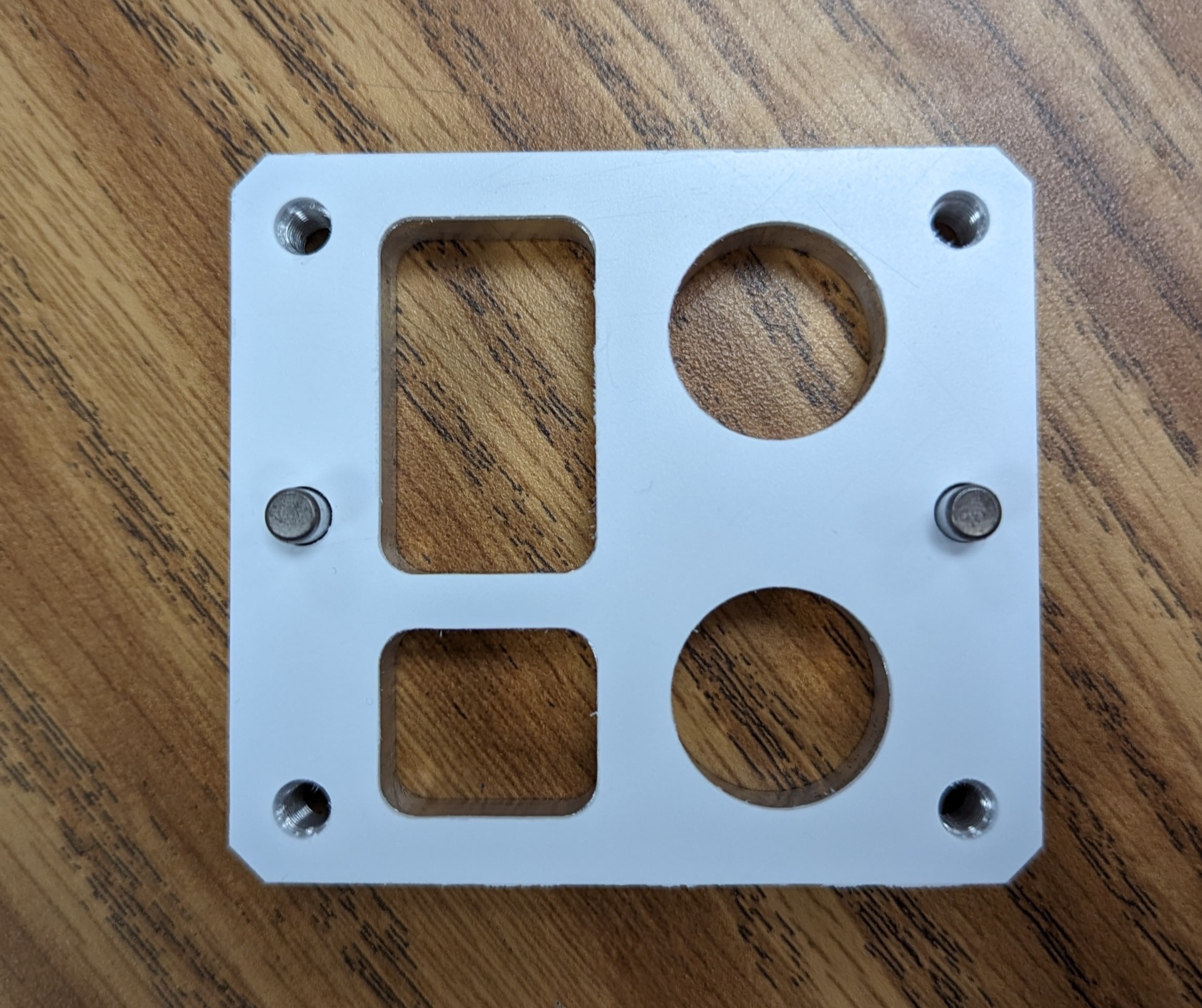
The aim of the Gasket Project was to create a PVC gasket that perfectly fit a specifically machined aluminum block. The first step of the process was to precisely measure the features of the block with calipers. The next step was to model the gasket in CAD software.
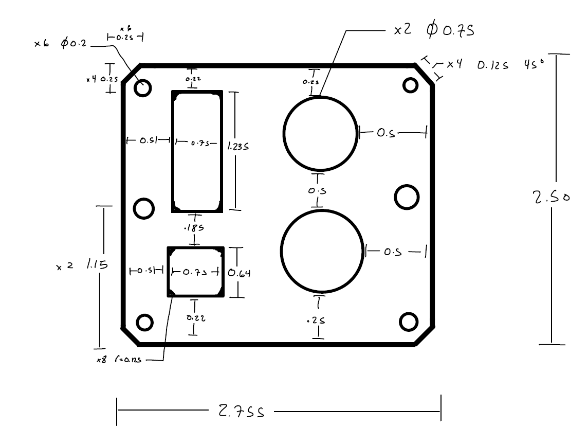
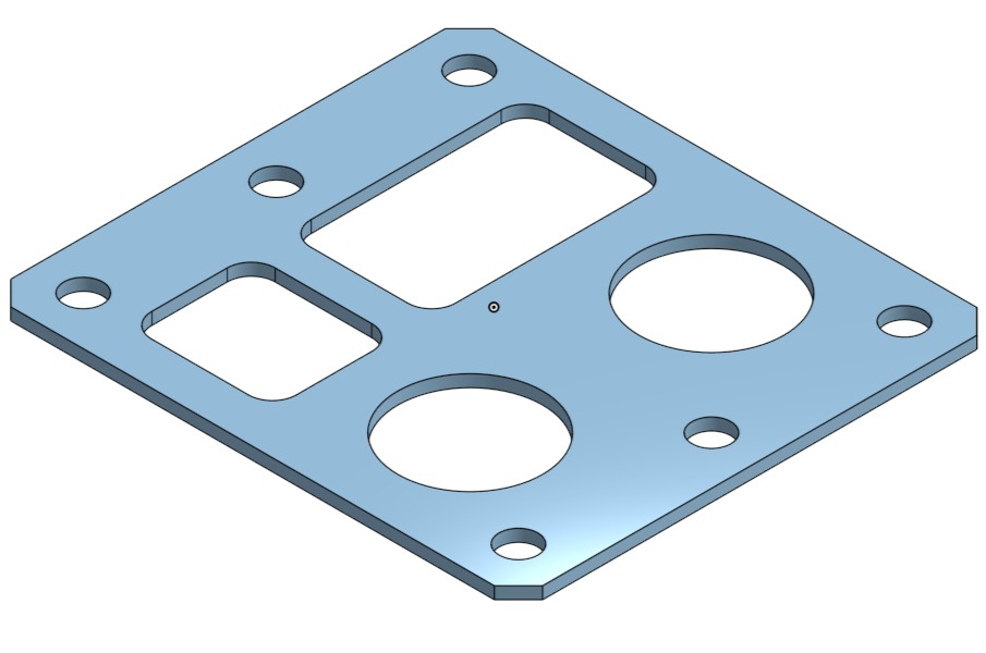
After the gasket had been modeled, it was imported into GibbsCAM, where the machining processes were specified, and the G-code for the mill was created. The CNC mill then cut the gasket, and the edges were deburred. This project emphasized the importance of tolerance and detailed design while providing an introduction to CNC machining.

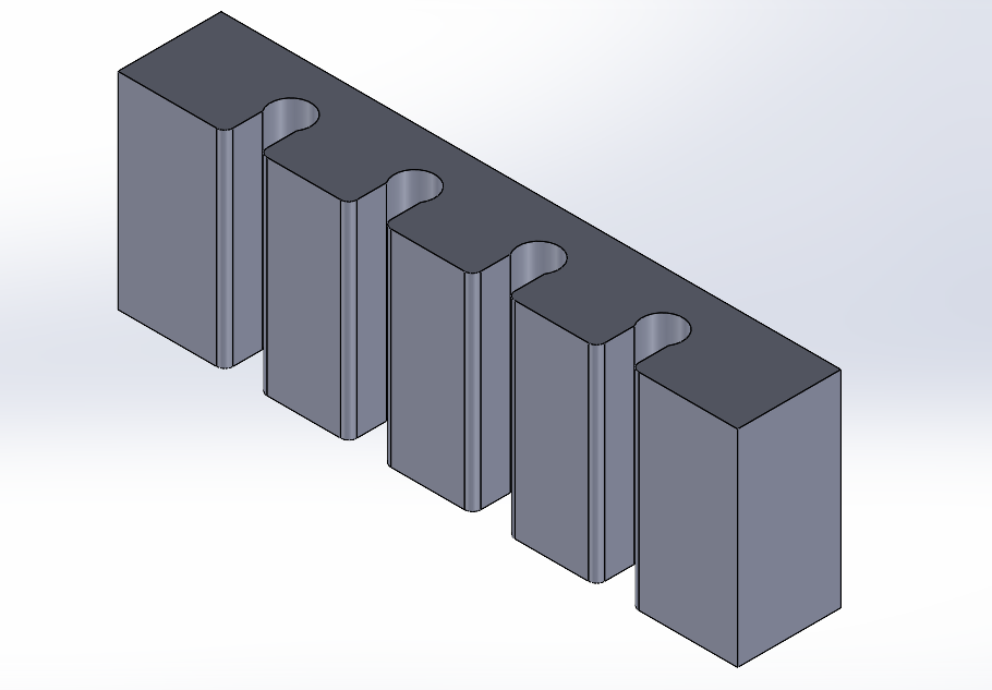
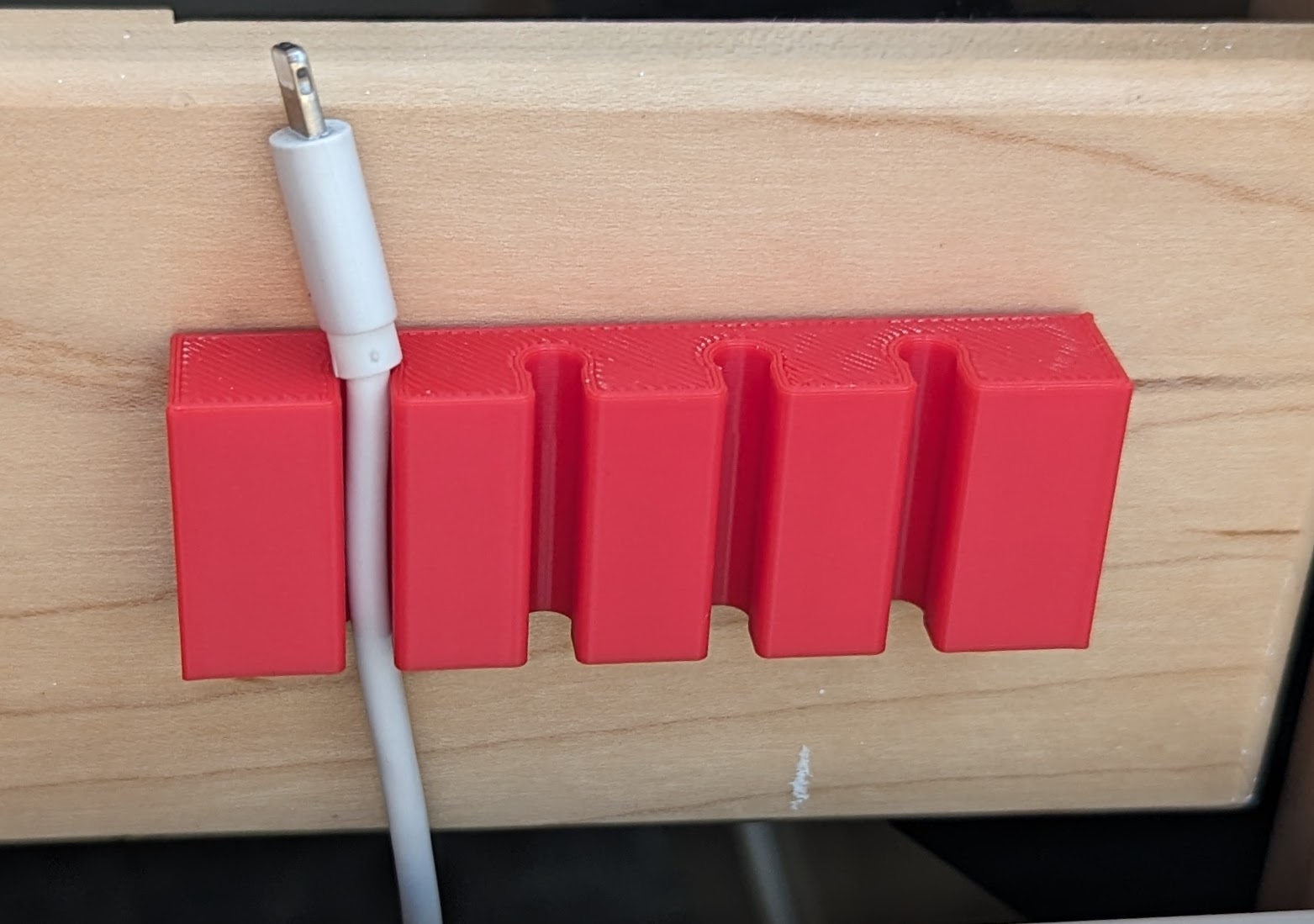
This project aimed to create a product to solve the problem of loose wires falling off of a bed or desk when not in use. The product needed to be easy to 3D print with simple geometry, be small enough to fit within the small build area of the printer, and fit securely on a large surface such as a bedpost or desk. The original design was extended to fit multiple cables, and the backside of the cable holder was designed as a flat surface to attach an adhesive pad. After creating a quick sketch of the product, the cable holder was modeled in CAD software and exported to be 3D printed.